Unit is in great shape and perfect working order.
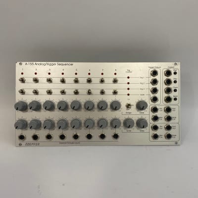
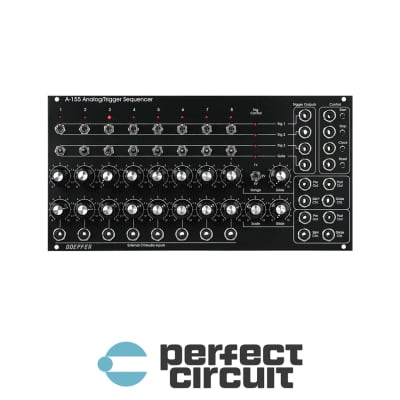
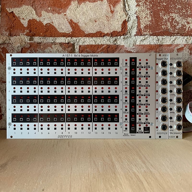
A-157 is a trigger sequencer subsystem that generates eight trigger signals controlled by a 8x16 LED/button matrix.
The subsystem contains three modules:
- A-157-1: 8 x 16 LED/button matrix and function adressing buttons/LEDs
- A-157-2: Trigger Output module
- A-157-3: Control Inputs module
The
LED/button matrix module A-157-1 is the core of the subsystem. It is
used to set or reset the trigger event on each of the 16 steps of each
of the 8 rows. In addition the buttons and LEDs of the matrix are used
for other functions too (like setting the first and last step of each
row or adressing the preset memory).
The Trigger Output module A-157-2 outputs the 8 trigger signals and has an LED display for each trigger available.
The Control Inputs module A-157-3 has manual controls and trigger
inputs available for the basic control functions start, stop, reset and
clock. In addition four functions inputs are available which will be
used in future firmware versions to assign these inputs to special
functions (e.g. shifting a row left or right by means of an external
gate/trigger signal or a second set of start, stop, reset and clock for
individual rows).
A-157-1
In addition to the main 8x16 matrix this modules contains also the buttons and LEDs for these functions:
-
Mute button for each row, these buttons are planned also as submenu buttons for future firmware version
-
Select
button for each row, used to address one or more rows for subsequent
functions (e.g. first step, last step, shift left, shift right ...)
-
Function
buttons/LEDs, the functions are divided into two levels, the second
level is invoked by the SHIFT button/LED on the buttom right position
-
The functions without SHIFT are printed black, the SHIFT-functions are printed in reverse
-
On
the front plate there are already printed some texts for
future/additional features/functions. Mainly in the SHIFT-plane. As
long as they are not explained in the manuals they have no function at
the moment and are only placeholders for the future. Future versions of
the firmware can be updated by the user via USB.
A-157-2
This
is the trigger/gate output module that has 8 sockets with assigned LEDs
available. The width of the output signal depends upon the width of the
incoming clock signal, i.e. the width of the output signals is the same
as the width of the incoming clock signal.
The level of the output signal is software controlled (i.e. not fixed to
a certain value) as each outputs is equipped with a separate DAC
(digital-to-analog converter).
A-157-3
This
module is the master control unit for Start, Stop, Reset and Clock. In
addition four function controls and inputs are available that will be
used in future firmware versions to address certain functions also from
external signals (e.g. shifting a row ). Each function has a manual
operated button and a control input. The voltage at each input has to be
+3V... +12V to trigger the function in question.
Important
technical note for A-157-3: The pin header JP2 at the bottom edge of
the pcb is unused so far. It is labelled "(OPTION) START/STOP/RESET
BREAKOUT" and is planned for a Start/Stop/Reset/Clock breakout module.
That's why the A-157-3 module is delivered without a cable connected to
JP2 !
Do no connect JP2 to the A-100 bus ! This will damage the A-157 modules and warranty is void !
The
three modules are internally connected via ribbon cables and can be
arranged also in another layout (e.g. A-157-2/3 on the right side of the
A-157-1 or in a row above or below). The modules are available only as a
complete set.
Power consumption: 80-350mA at +12V and 20mA at -12V
Depth: 45mm
HP : 52